Derek L’Hirondelle

Building a DIY Preset Switch for Meris Pedals

Preset Switch Complete.jpg

Anyone who’s into guitar pedals will know that Meris is one of the most popular boutique brands on the market right now. Which is impressive, because they only started a building pedals in the spring of 2017. Before that, they created modules for 500 series-sized pro audio gear.

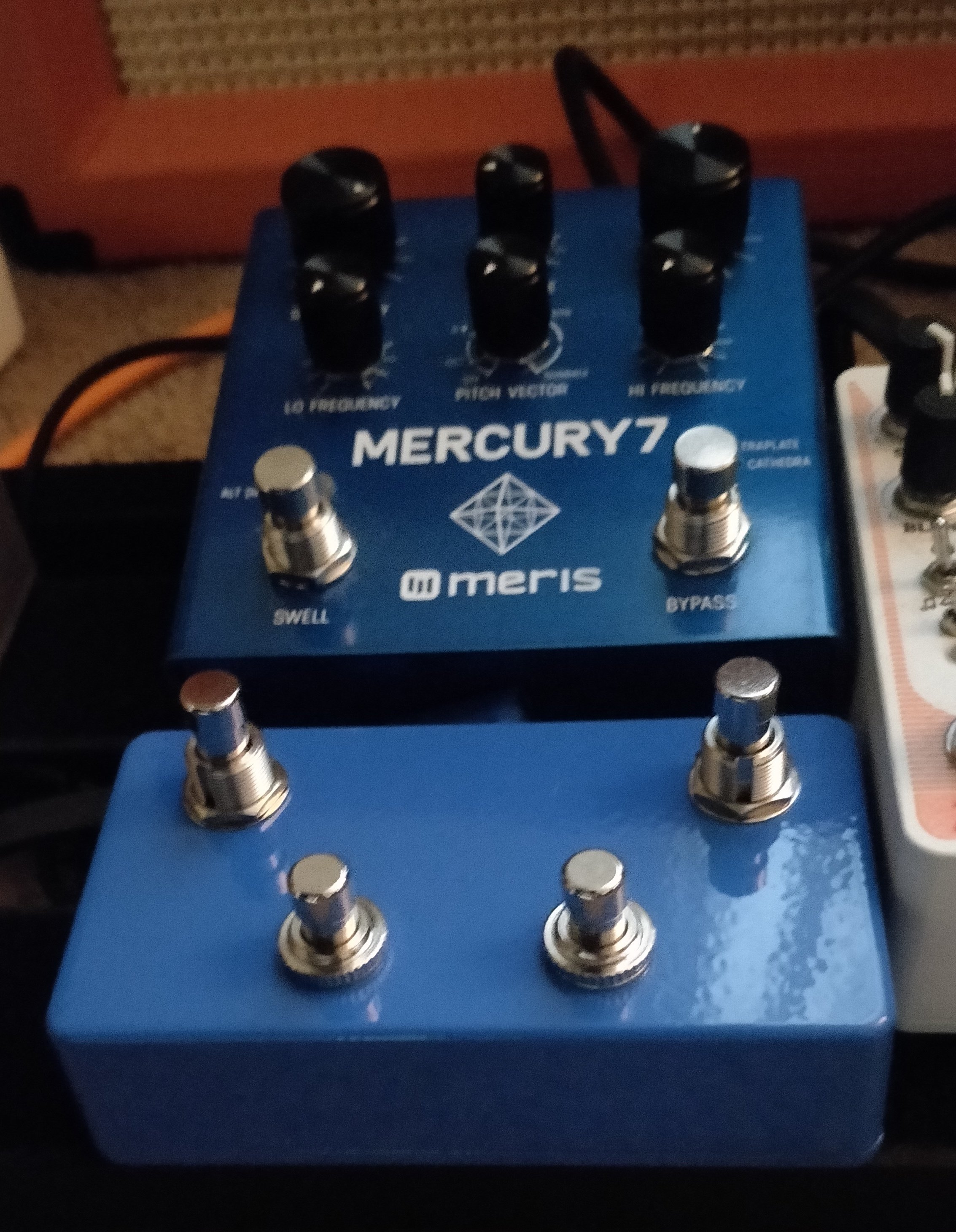
My first Meris pedal was the PolyMoon that I received in a trade and not too long after that, I bought the Mercury7. These are very feature-heavy pedals but they can be as simple or as complicated as you want. All of the knobs have secondary functions, which makes these ideal for people who love to tweak settings for hours and push the pedal to create some absolutely wild sounds.

One drawback of having such a deep pedal is that you’ll eventually want to save your settings and come back to them later. Luckily, Meris pedals are able to save 16 presets that are accessible via MIDI. However, this isn’t immediately possible without some external hardware.

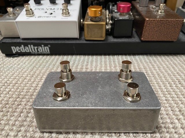
Meris sell a preset switch that can access four presets for $99. They also sell a MIDI to TRS converter for the same price, but you’ll need a MIDI controller to work with it and that will be another $200+. I’m going to show you how to create your own preset switch (with the help of some power tools), that can recall up to four presets for about $12. I chose to go with three presets so my enclosure would feel less crammed, but it’s completely up to you.


What you’ll need:

  • an enclosure (I used a 1590B-sized ones)

  • a 1/4” stereo jack

  • SPST-NO (Normally Open) momentary footswitches (one for each preset, I used these)

  • 3 resistors (100 ohm, 240 ohm, and 510 ohm)

  • approximately 6 inches of electrical wire

  • a power drill

  • 3/8” drill bit

  • 1/2” drill bit (or a stepped drill bit that covers both sizes)

  • a soldering iron

  • solder wire (electrical)


Let’s get started:

Here’s an example from another project.

1) Mark the enclosure for where you’re going to be drilling. The 3/8” drill bit is for the 1/4” jack for the TRS cable that will be connected to it. So it would make sense to place the hole for this on the side somewhere. The 1/2” drill bit is for the footswitches, which will be on the face of the enclosure. When doing this, I usually cover the enclosure in masking tape, draw lines with a ruler, and mark measurements to get so that the holes line up in the most aesthetically pleasing way possible. (The picture to the right is an example of my measurements from another project.)


2) Drill the holes. If possible, use a centre punch to create an indent in the enclosure to help guide the drill. Starting with a smaller bit and working your way up will most likely result in a cleaner and more precise final hole (a stepped drill bit is also great for this!).


3) Connect the footswitches and jack to the enclosure. (You might have to angle a footswitch or two so they won’t touch the jack.)


4) It’s time to start placing wires and soldering!

Each switch has a specific resistor value that the pedal reads. The Tip and Ring of the jack are connected together, and then connected to the resistor for each switch. For simplicities sake, the resistors can be directly soldered to the jack and the lugs of the footswitches. The other side of each switch is tied together and connected to the Sleeve of the TRS jack, as shown in the diagram below. I made a crude drawing below for you to follow along with (based on this schematic).

Preset Switch Diagram.png

The final result should look something like this:

Preset Switch Wiring.jpg

You can see how two of the resistors are connected to the Tip of the jack, and the other is soldered to the Ring. It doesn’t really matter because of the wire connecting the Tip and Ring. IMPORTANT: Please ensure that all wiring that isn’t coated (the resistors) aren’t touching anything they aren’t supposed to.

This works because Meris pedals are constantly sending and receiving electrical current out of the EXP jack and when you press any of the footswitches, the resistors cause a change in the amount of electricity that the pedal is receiving, the amount of change is what tells it which preset was selected.

To add the fourth switch, repeat the same process, except instead of using a resistor, you’ll wire directly to the fourth switch as shown below.


5) You’re done! (potentially)

Screw the back plate onto the enclosure, insert a TRS cable into the jack, and connect it to the EXP jack on the pedal. If you haven’t already, you may need to setup the pedal so it knows the a preset switch has been connected. Below are instructions from a Meris manual on how to do that. It will always be the bottom right knob. On the Mercury7, it is labeled “Hi Frequency,” PolyMoon is “Dynamics,” Enzo is “Modulation,” etc. Set the Expression Mode to “Preset”.

Preset Switch Configure 2.png

By now, hopefully everything should be working! If not, go over your wiring and make sure you did all the steps right and that everything is connected properly.

Meris DIY Preset Switch

And just like that, you now have your own preset switch and you were able to save a couple bucks! Let me know if you have any questions or comments regarding building this. I’d love to see any completed builds as well.

Bonus: a few other companies use a very similar way of externally controlling their pedals (Strymon, Red Panda, etc.), just with different resistor values. So you could easily create preset switches and controllers for a whole bunch of other pedals if you’d like to!

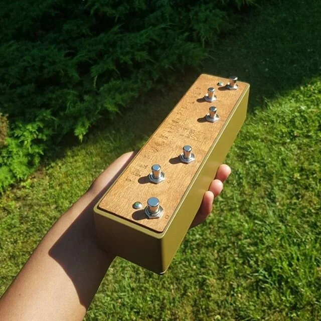
Below are some completed projects from people who have reached out. I’m honestly amazed at how well these turned out. Beautiful!

Recreating the THX Deep Note

THX Deep Note.png

I recently stumbled upon the original sheet music for the THX Deep Note and knew that I had to recreate it. I had an hour to kill over the weekend so I decided to take a stab at it. The only equipment used in the recording was my Moog Sub Phatty direct into Logic.

In the score, it mentions that each note should be played with three voices per note. Since the Moog only has two oscillators, I decided to hard sync the two together and add de-tuning later in the DAW. Another creative liberty I took was that instead of having the starting note in a tight cluster and gliding to its ending pitch, I arbitrarily picked starting notes that were several octaves away, making the glide even more dramatic. On the higher notes, I added a little bit of modulation with the Sub Phatty’s LFO section.

When attempting this yourself, you really only need a synthesizer with some way to slide between notes smoothly. This may be called many things, depending on the manufacturer. On Moog synths, this is called “Glide,” Roland and Korg call their’s “Portamento,” and I’ve seen other’s use “Glissando.”

After recording a take of each of the notes. I used the Micro Shift plugin by Soundtoys to detune the notes and create the “3 voices per note, slightly detuned” effect mentioned on the score. Besides that, I also used some light bus compression, a low-pass filter sweep at the beginning, some reverb, and a fade out at the end.

If I were to do it again, I probably wouldn’t choose to use a sawtooth oscillator, as the really low notes were playing below audio rate and sounded more like a LFO when solo’d. It’s not immediately obvious when listening but I know it’s there.

If this inspires you to try it yourself, I’d love to here what you come up with! You can contact me here.

My Custom Morphagene Reels (and How To Create Your Own!)

When I first got into Eurorack, the Make Noise Morphagene was one of those modules that seemingly everyone had. The most inspiring patches usually involved the Morphagene in one way or another and it’s no surprise as to why. It can be used in many ways but what always spoke to me the most, is it’s ability to take pre-recorded material and warp and mangle it using the knobs and the CV (Control Voltage) inputs. This pre-recorded material could be anything from field recordings, past jams, various cool sounds, percussive loops, human speech, sections from songs, etc.

In order to create your own, you’ll need a DAW that can export at a sample rate of 48,000 kbps and a bit depth of 32-bit Floating Point. The ability to store metadata within the file for Splice markers is also preferred but not 100% necessary. I chose to use Logic Pro X (10.4) for this purpose. You’ll also need a way to write to a Micro SD if you plan on using them with your own Morphagene. I use this adapter.

I happened to have several hours worth of recorded Eurorack jams on hand so I figured that would be a good place to start. I picked about 10 of the shortest ones and the cultivated from there. I tried to pick the pieces with enough variation to keep it interesting, yet have a very defined mood and tone throughout. From past experience with the Morphagene, it seemed like shorter Splices yielded better results so I tried to keep them fairly short. In longer sections that sounded great as a whole, I’d add cuts throughout, but I’d keep both parts beside each other. Any section that seemed redundant or that just wasn’t very interesting got axed. All of these edits are good because they’ll eventually act as Splice markers later on.

After you reach a point where you’re happy with your edits. Highlight the Regions and select “Create Markers From Regions.” These markers will be stored as metadata and the Morphagene will interpret them as Splice markers.

From here, there are three paths which you can take that essentially accomplish the same goal:

Option 1: Export Track as Audio File

If you choose this option, make sure you have “Trim Silence at File End” selected or else your file will be the entire length of your Project. You could always drag the Project End marker to the where your audio ends as well.  

Option 2: Export Region as Audio File

I originally tried to use export using this method but for some reason Logic wouldn’t let me select WAVE with 32-bit Float, it only gave me the option for AIFF. Probably just a bug. When I tried later, after using Option 1, it allowed me to select WAVE now. That could be the possible work-around.

To use this method, highlight all the Regions you wish to use. Select “Join” to create one large Region. 

Option 3: Bounce Highlighted Area

In my mind, this is the easiest way and I will continue doing it this way in the future. Just highlight the Regions you wish to Bounce and hit ⌘B (command+B).

08 Bounce.png

You can choose whatever of the options above. They all export at the required quality and store metadata for the Splice markers. Just make sure that you match the settings in the pictures above before exporting.

I keep a folder specifically for Morphagene Reels and audio that can be used for Reels in the future.

09 Folder Management.png

Make sure you rename the files "mg1.wav", "mg2.wav", etc. before loading them onto the Micro SD. If you pass 9, switch the naming convention to “mga.wav”, “mgb.wav”, etc. The Micro SD can have up to 26 Reels on it at any given time.

10 Rename Files.png

This was my first experience at making my own Reels for the Morphagene and I can’t wait to create more and experiment in the future. I have a ton of field recordings, songs, and random percussive sounds that I think could be great fun to work with. Click Here to download my Morphagene Reels,

Did you create anything after reading this or have any comments regarding the article? Feel free to get in touch!