Anyone who’s into guitar pedals will know that Meris is one of the most popular boutique brands on the market right now. Which is impressive, because they only started a building pedals in the spring of 2017. Before that, they created modules for 500 series-sized pro audio gear.
My first Meris pedal was the PolyMoon that I received in a trade and not too long after that, I bought the Mercury7. These are very feature-heavy pedals but they can be as simple or as complicated as you want. All of the knobs have secondary functions, which makes these ideal for people who love to tweak settings for hours and push the pedal to create some absolutely wild sounds.
One drawback of having such a deep pedal is that you’ll eventually want to save your settings and come back to them later. Luckily, Meris pedals are able to save 16 presets that are accessible via MIDI. However, this isn’t immediately possible without some external hardware.
Meris sell a preset switch that can access four presets for $99. They also sell a MIDI to TRS converter for the same price, but you’ll need a MIDI controller to work with it and that will be another $200+. I’m going to show you how to create your own preset switch (with the help of some power tools), that can recall up to four presets for about $12. I chose to go with three presets so my enclosure would feel less crammed, but it’s completely up to you.
What you’ll need:
an enclosure (I used a 1590B-sized ones)
a 1/4” stereo jack
SPST-NO (Normally Open) momentary footswitches (one for each preset, I used these)
approximately 6 inches of electrical wire
a power drill
3/8” drill bit
1/2” drill bit (or a stepped drill bit that covers both sizes)
a soldering iron
solder wire (electrical)
Let’s get started:
1) Mark the enclosure for where you’re going to be drilling. The 3/8” drill bit is for the 1/4” jack for the TRS cable that will be connected to it. So it would make sense to place the hole for this on the side somewhere. The 1/2” drill bit is for the footswitches, which will be on the face of the enclosure. When doing this, I usually cover the enclosure in masking tape, draw lines with a ruler, and mark measurements to get so that the holes line up in the most aesthetically pleasing way possible. (The picture to the right is an example of my measurements from another project.)
2) Drill the holes. If possible, use a centre punch to create an indent in the enclosure to help guide the drill. Starting with a smaller bit and working your way up will most likely result in a cleaner and more precise final hole (a stepped drill bit is also great for this!).
3) Connect the footswitches and jack to the enclosure. (You might have to angle a footswitch or two so they won’t touch the jack.)
4) It’s time to start placing wires and soldering!
Each switch has a specific resistor value that the pedal reads. The Tip and Ring of the jack are connected together, and then connected to the resistor for each switch. For simplicities sake, the resistors can be directly soldered to the jack and the lugs of the footswitches. The other side of each switch is tied together and connected to the Sleeve of the TRS jack, as shown in the diagram below. I made a crude drawing below for you to follow along with (based on this schematic).
The final result should look something like this:
You can see how two of the resistors are connected to the Tip of the jack, and the other is soldered to the Ring. It doesn’t really matter because of the wire connecting the Tip and Ring. IMPORTANT: Please ensure that all wiring that isn’t coated (the resistors) aren’t touching anything they aren’t supposed to.
This works because Meris pedals are constantly sending and receiving electrical current out of the EXP jack and when you press any of the footswitches, the resistors cause a change in the amount of electricity that the pedal is receiving, the amount of change is what tells it which preset was selected.
To add the fourth switch, repeat the same process, except instead of using a resistor, you’ll wire directly to the fourth switch as shown below.
5) You’re done! (potentially)
Screw the back plate onto the enclosure, insert a TRS cable into the jack, and connect it to the EXP jack on the pedal. If you haven’t already, you may need to setup the pedal so it knows the a preset switch has been connected. Below are instructions from a Meris manual on how to do that. It will always be the bottom right knob. On the Mercury7, it is labeled “Hi Frequency,” PolyMoon is “Dynamics,” Enzo is “Modulation,” etc. Set the Expression Mode to “Preset”.
By now, hopefully everything should be working! If not, go over your wiring and make sure you did all the steps right and that everything is connected properly.
And just like that, you now have your own preset switch and you were able to save a couple bucks! Let me know if you have any questions or comments regarding building this. I’d love to see any completed builds as well.
Bonus: a few other companies use a very similar way of externally controlling their pedals (Strymon, Red Panda, etc.), just with different resistor values. So you could easily create preset switches and controllers for a whole bunch of other pedals if you’d like to!
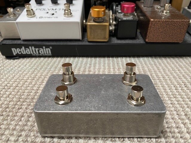
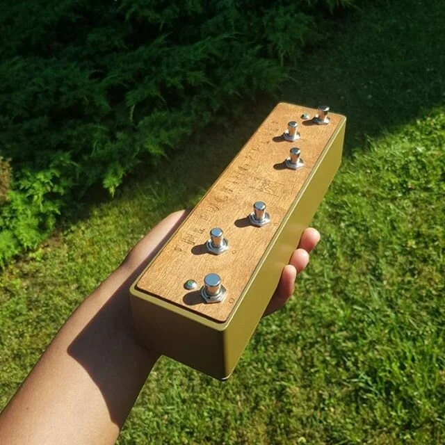
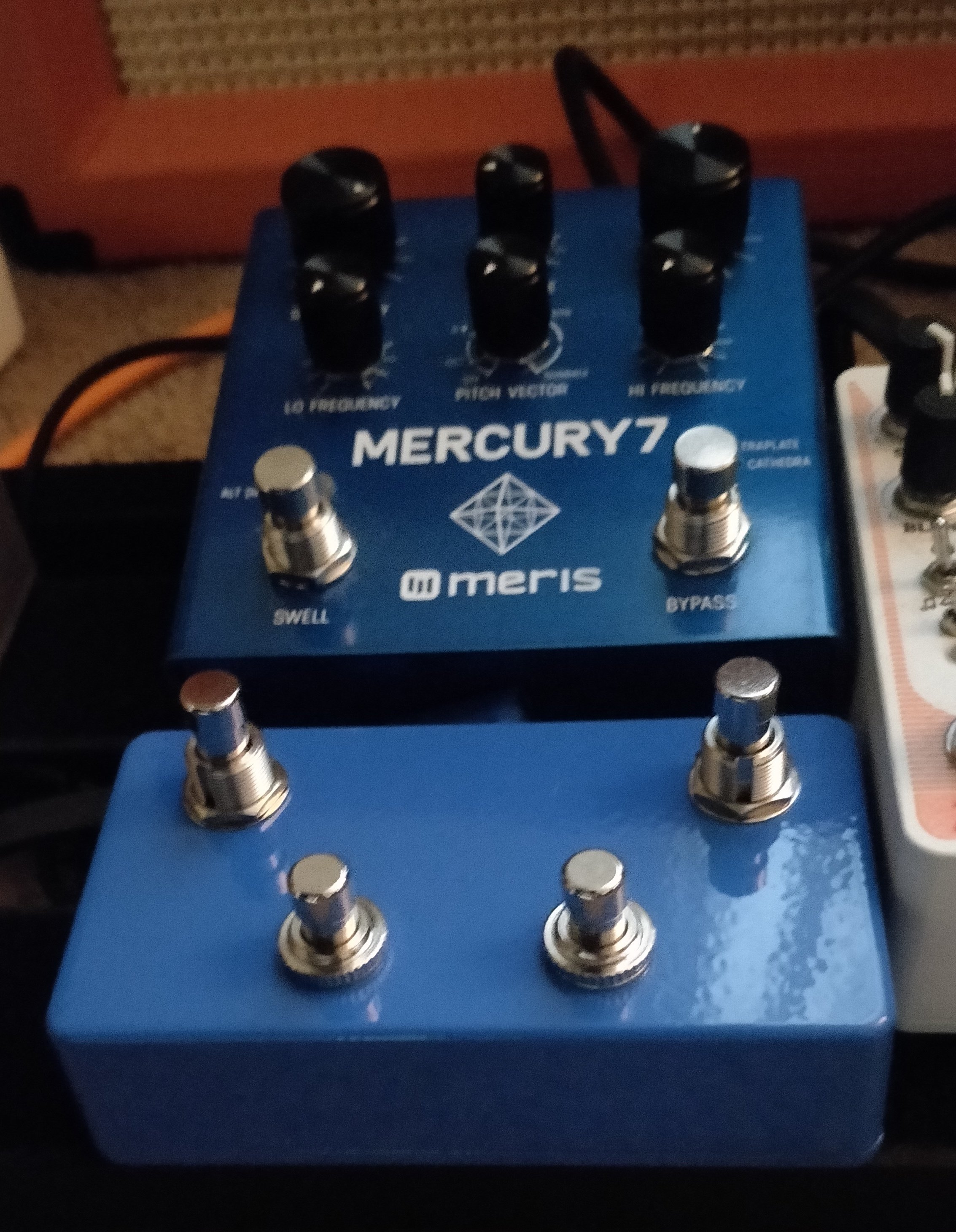
Below are some completed projects from people who have reached out. I’m honestly amazed at how well these turned out. Beautiful!


